
70s Twin Reverb rebuild
This morning I spent a couple of hours evaluating this amplifier for a customer who wants to sell it.

It's been a while since I've seen one and I'd forgotten just how ridiculously heavy they were, especially this example with the JBL speakers. I could barely lift one twenty years ago let alone now. How often would one need 135 watts in a combo these days?

Before I took the chassis out of the cabinet I plugged in a guitar and noticed that the tone was very weak and bass light. There were also some scratchy pots and the reverb wasn't functioning. I checked the speaker wiring and noticed they had been wired out of phase with each other! Fixing that restored some of the low end but there were still other issues that needed addressing such as the high level of 100Hz hum.
Removing the amp from the chassis revealed a couple of anomalies.......

...an extra capacitor had been fitted at some point, but in this position (the main bulk storage) it would usually be part of a pair with voltage dividing resistors. I turned the chassis over and removed the cap board cover and sure enough.......

....there was a capacitor missing. The orange replacement cap was too big to fit under the cover so the tech who fitted it had put it inside the chassis. Perhaps it was a quick fix to get through a gig way back then?
On to the reverb. Using a dummy load, signal generator and scope I probed the send to the spring reverb unit. Nothing. I measured the voltage each side of the primary of the reverb transformer. Identical at 425 volts meaning no current flowing. No voltage on the cathode of the 12AT7 driver either so a duff valve. I removed the valve cover and sure enough....
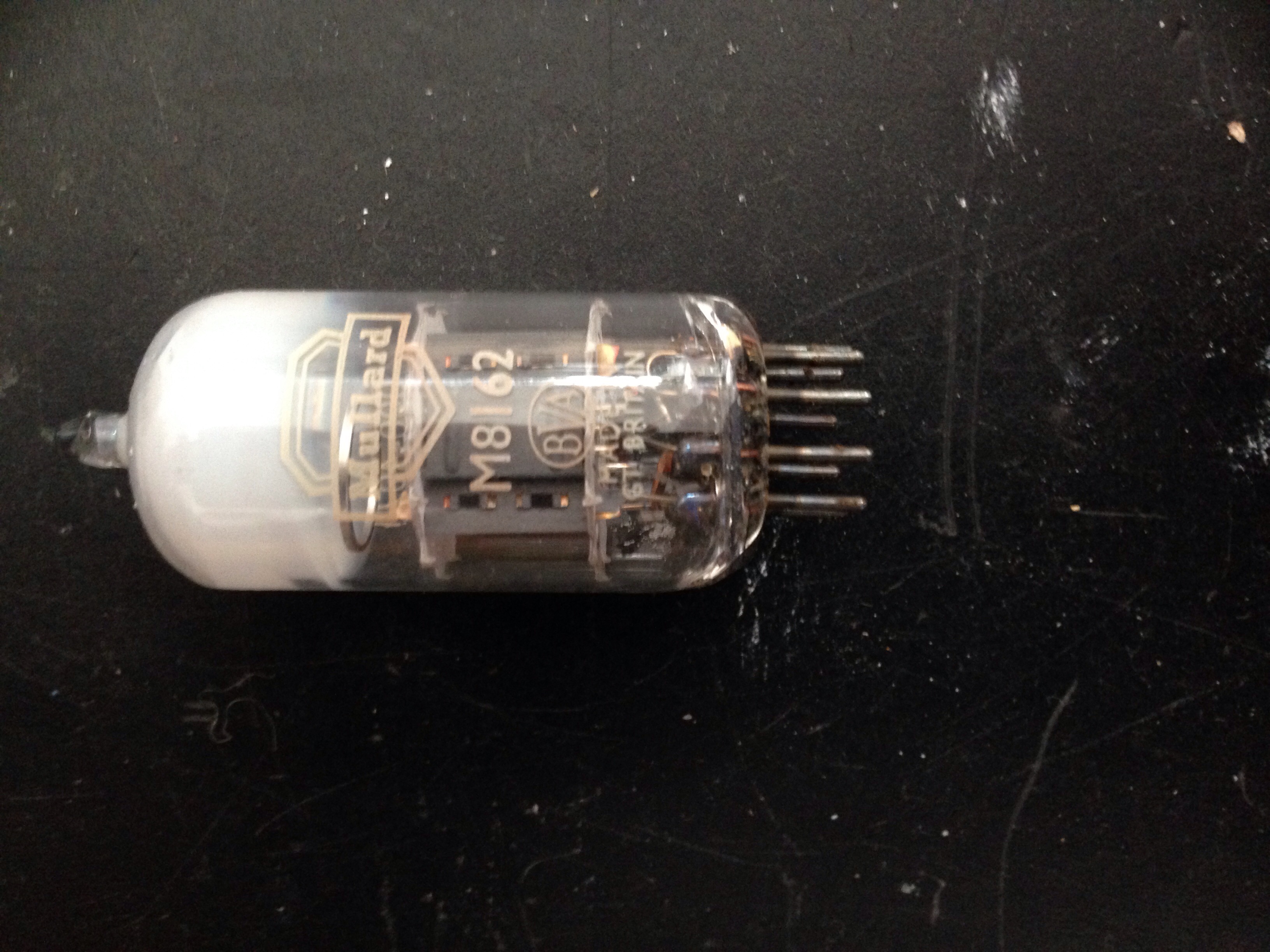
...a Mullard equivalent with a cracked envelope. I put in a replacement and scoped the output again and the signal was there. I hooked up the spring reverb unit but still there was no reverb at the output of the amp. I was expecting the problem to be with the spring itself but before measuring it I checked the leads feeding the spring unit and both were open circuit. A temporary hi-if lead was installed and the reverb was working perfectly.

Now the tremolo on these amps like most Fender amps needs the foot switch to make it work - it's a simple design - the closing of the foot switch enables the oscillator. The foot switch for this amp was absent so I shorted the socket with a crock clip lead. The tremolo worked but clicked. A quick check with a multimeter revealed some DC across the photocell which is most likely from a leaking inter stage coupling cap. This would also explain the scratchy tone pots.
A good thing to do when servicing guitar amps is to connect a speaker and using a well insulted screwdriver handle gently tap the amplifier all over inside and out to reveal any bad connections or mechanical issues. Do it with and without a signal. In this case a number of issues were found including one output valve who's heater would turn on and off probably due to a poor connection in the valve socket. It's a straightforward job to retension the sockets.
I enjoy working on these amps. They were designed to be serviceable which was a part of Leo Fender's philosophy from the beginning. Fender used this style of construction on all their amplifiers right into the early eighties until 'modern', but in my mind inappropriate mass production techniques were employed. Most amplifiers made nowadays use printed circuit board mounted pots, switches and connectors and lots of inter board connectors. They usually have to completely dismantled to replace any components. None of these makes for easy and reliable servicing.
I doubt many of today's mass produced amplifiers will be around in 40 years just needing a few parts replacing like this Twin.