FX loops pros and cons
Many modern amplifiers have effects loops principally to allow time delay effects to be applied after the amplifier's distortion producing circuitry. But effects loops are very rarely found on old vintage style amplifiers. This series of articles looks in depth at how effects loops came about, their limitations, how they can affect your tone and how you need to set up your gear to use them to their best.
In the early days of electric guitar amplification it was never intended that the amplifier would distort. In fact many manufacturers would employ techniques to minimise distortion. (This is one reason why guitar amplifier output power kept increasing to well over 100 watts, the 135 watt ultra linear Fender Twin Reverb I rebuilt a few months ago being a prime example). During the 50's output valve distortion became an integral part of the rock n roll guitar sound, probably as a result of guitarists turning the amplifier volume up to be heard over the noise of the audiences. The extra harmonics introduced when the amp went into clipping also increased the perceived volume of the amplifier.
The 60's saw the introduction of fuzz pedals to produce distortion, but it wasn't until the 70's that guitar amplifiers were being produced that were designed to distort. The Mesa Boogie MkI was the first high gain amp that produce reasonable amounts of pre amp distortion and by the end of the 70's the MkIIC+ had separate master volume for the lead channel, an effects or FX loop, spring reverb and EQ, all foot switch-able. It had taken few iterations (these were pioneering times) to get the FX loop at the right point in the signal chain and able to work with pedals without overloading them. There were also features, albeit fairly crude ones, to vary the power output level, indicating that it was recognised that power amp distortion was desirable. In the 80's the MkIII introduced a third crunch/rhythm mode and not much has changed since then really. Foot switch-able channels, gain, reverb and FX loops are the standard feature set for many guitar amps. The implementation may have improved but essentially they offer the same facilities.
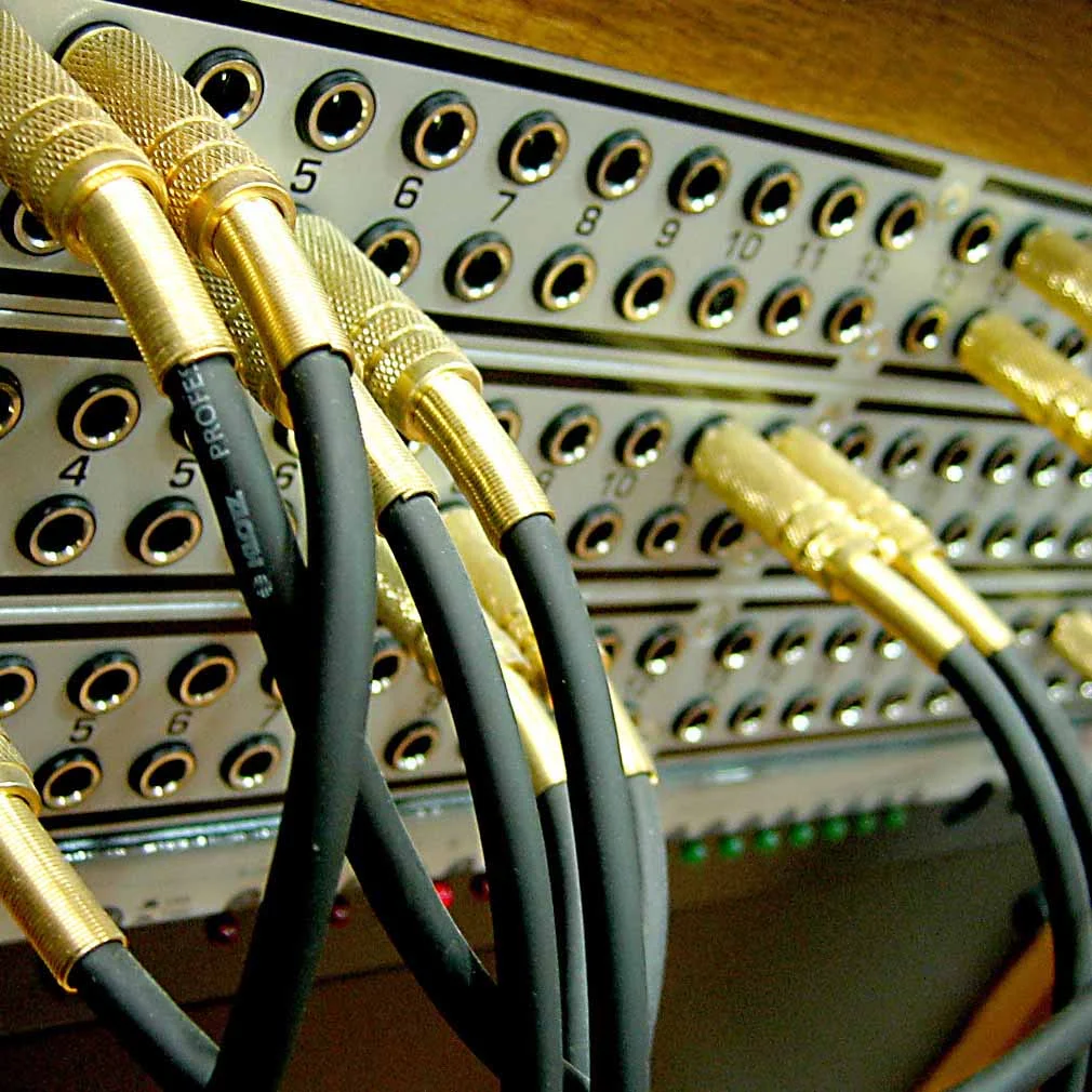
FX loops were derived from recording studio patchbays
The FX loops as we know them are adopted from the world of mixing consoles where they are known as 'Inserts' and comprise of a pair of sockets on a patch bay. One socket is an output or send and the other an input or return. The return socket usually has a switching contact to connect it to the send unless a plug is inserted into it. This is called normalising, and specifically, in this case, 'half Normalising'. It negates the need for a cable when the insert is not being used, but can also be the source of troublesome intermittency and distortion if the contact becomes corroded (as they often do when exposed to moisture, smoke, beer etc). By the way, 'full normalising' has a switching contact on both send and return.
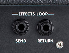
A typical basic FX loop on a guitar amplifier
Signal wise they are located after the microphone pre amplifier, where the signal is at line level and is of a standardised RMS and maximum level. They are used to patch in compressors, noise gates, delays and other processors, which are also designed to operate at the same standardised levels.
Now the world of valve guitar amplifiers is far removed from that of the pro audio world. Peak signal levels in valve amplifiers reach hundreds of volts rather than the ten or so found in a solid state mixer. And there is no standard for the RMS operating level. This presents the guitar amp designer with some problems - how to correctly match the signal levels on the amplifier to those in the effects processors.
What do we mean by match? Well all audio equipment has a dynamic range defined by the difference between the lower level of noise generated by the equipment (noise floor) and the upper level of the point at which it starts to distort. It is good practise to keep levels as high as possible to minimise the effect of the noise floor but not so high that the equipment produces unwanted distortion. We are matching the dynamic range of the two pieces of interconnected equipment, and when we do this we usually create a safety margin we call 'headroom'.
Headroom is the difference between the average level we expect to see and the higher level at which the equipment clips or enters distortion and is commonly expressed in decibels or dB. It is important that we consider the type of signal we are dealing with. With a highly saturated signal there is maybe only 2 or 3 dB difference; with a very clean electric guitar signal the peak levels can be 20dB or more greater than the average level. We would also expect to see the noise floor at least 70 to 80dB below the clipping point of the equipment. So on an amplifier with clean and overdriven channels the pedals or processors in the FX loop and the FX loop circuitry itself need to cope with a very wide dynamic range. What is also important is that by allowing more headroom we reduce the signal-to-noise ratio (SNR).
Diagramatic representation of audio dynamic range
So how do we make sure the amp is matched correctly to the devices in the FX loop? On a mixing console we have signal level meters, and on the 'outboard' processing gear there are usually controls to set the input and output levels and another meter or set of LEDs to allow the controls to set the correct levels. Many rack based processors for guitar have similar input and output levels and metering. The big problem is when we want to put pedals in the FX Loop.
A typical rack processor with input metering and level controls
Rack processors tend to operate at higher levels - up to to +20dBu or around 30 volts peak to peak, although some also allow for lower level operation to comply with the -10dBv standard for semi pro audio equipment. Although there are exceptions, most guitar FX pedals are designed to operate on a 9 volt power supply and this usually means there is a limit to the maximum signal level that they can accommodate of something lower than this - usually something in the region of 5 volts peak to peak.
Guitar effects pedals operate at a lower signal level than 'pro-level' rack equipment
So we have a valve amplifier with peak voltages of around 120 volts, rack equipment around 30 volts and pedals at 5 volts. Let's say we add an attenuator to the FX send to drop the amps 120 volts down to 5 volts and then add a gain stage to restore the 5 volts from the output of the pedal back to the 120 volts for the amplifier. That's all fine if we are running the amplifier so there is 120 volts at the phase splitter. But what if we are running the amp at a lower level say to practise or because we don't want to push the power amp into distortion. In this case we are using a much lower level of signal in the pedal and don't make use of the available dynamic range. When we recover the signal in the amplifier our effective noise floor has risen and the dynamic range is now the difference between the signal going through the pedal and the noise floor of the pedal. You can see that the purity of the signal is being compromised.
All is not lost however. Most amplifiers that have FX loops have a master volume control. If this is located after the FX loop then the channel volume controls can be set to always utilise the maximum dynamic range of the pedals in the loop and the master volume can be used as - er - a master volume! Bingo problem solved . Well it would be if we knew that we were driving the pedals with the optimum signal level.
To be continued.................